| The MAGLEV Levitation System |
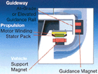
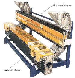
Electronically controlled support magnets located on both sides along the entire length of the vehicle pull the vehicle up to the ferromagnetic stator packs mounted to the underside of the guideway.
Guidance magnets located on both sides along the entire length of the vehicle keep the vehicle laterally on the track. Electronic systems guarantee that the clearance remains constant (nominally 10 mm). To hover, the MAGLEV requires less power than its air conditioning equipment. The levitation system is supplied from on-board batteries and thus independent of the propulsion system. The vehicle is capable of hovering up to 30 minutes without external energy. While travelling, the on-board batteries are recharged by linear generators integrated into the support magnets.
|
|
  |
| The MAGLEV Guideway Systems |
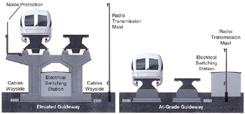 |
The MAGLEV hovers over a single or double track guideway. It can be mounted either at-grade or elevated on slim columns and consists of individual steel or concrete beams up to 62 m in length.
To change tracks, bendable switches are used which consist of a continuous steel beam which is elastically bent by means of electro-mechanical setting drives. Low speed switches, approx. 78 m long, are used to change tracks near stations and can be passed over in the turnout direction at 100 km/h (in the straight direction at full operating speed). High speed switches, approx. 150 m long, are used where higher turnout speeds are required (200 km/h turnout speed and in the straight direction at full operating speed).
Take a look at a switch in action.
|
|
MAGLEV Propulsion and Power |
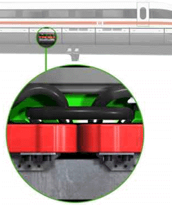 |
The MAGLEV is propelled by a non-contact, long-stator linear motor which is installed in the guideway and functions like a rotating electric motor with the stator cut open and stretched out below the guideway.
Electric current in the cable windings generates a travelling magnetic field which pulls the vehicle along without contact. The support magnets form the exciter (i.e. the rotor). The speed is variable by controlling the frequency of the current. Changing the direction of the field of the travelling wave results in non-contact braking of the vehicle because the motor is converted into a generator. The braking energy can then be fed back into the power grid in the form of electric energy.
|
|
| MAGLEV Vehicle Chassis |
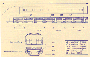 |
MAGLEV vehicles comprise a minimum of two sections, each with approx. 90 seats on average. According to application and traffic volume, trains may be composed of up to ten sections (two end and eight middle sections).
However, the MAGLEV is suitable for transporting goods as well. For high-speed cargo transport, special cargo sections can be combined with passenger sections or assembled to form dedicated cargo trains (payload up to 18 tons per section). As the propulsion system is in the guideway, neither the length of the vehicle nor the payload affect the acceleration power.
|
| More MAGLEV Technology Information |
Transrapid
Railway Technical Research Institute
Innovative Transportation Technologies
Principle of Superconducting Maglev
THE UAH MAGLEV HOME PAGE
MAGLEV - A Physics Viewpoint
Fundamentals of MAGLEV |
|
|
|
|
| |
|
| 1 |
2 |
3 |
4 |
5 |
6 |
7 |
| 8 |
9 |
10 |
11 |
12 |
13 |
14 |
| 15 |
16 |
17 |
18 |
19 |
20 |
21 |
| 22 |
23 |
24 |
25 |
26 |
27 |
28 |
| 29 |
30 |
|
|
|
|
|
|
|


